
Late June Status Update
June, 2025
I’m sitting at home today, waiting on an air conditioner service company to come by. We lost ours around 6pm last night. The daily temperature hovers around 92F, with 85%+ humidity, and thankfully the local realtors and maintenance folks know how urgent the issue is.
Driving into the boatyard!
I’ve been lax in updating, in part because I’ve been consumed by work aboard the boat. Dan and Kika of Sailing Uma fame have mentioned how despite their architecture degrees, the most valuable skillset they gained from their education was Kika’s project management training.
I’m realizing as we reach mid-summer how easy it is to get pulled into multiple projects, and how challenging the balancing act can be. Aside from the insufferable geekery below, we’ve also been learning to surf! We were fortunate enough to have our initial lessons from Jason Latham, a Team USA world class champion, but also an incredibly mellow (and insanely talented) guy.
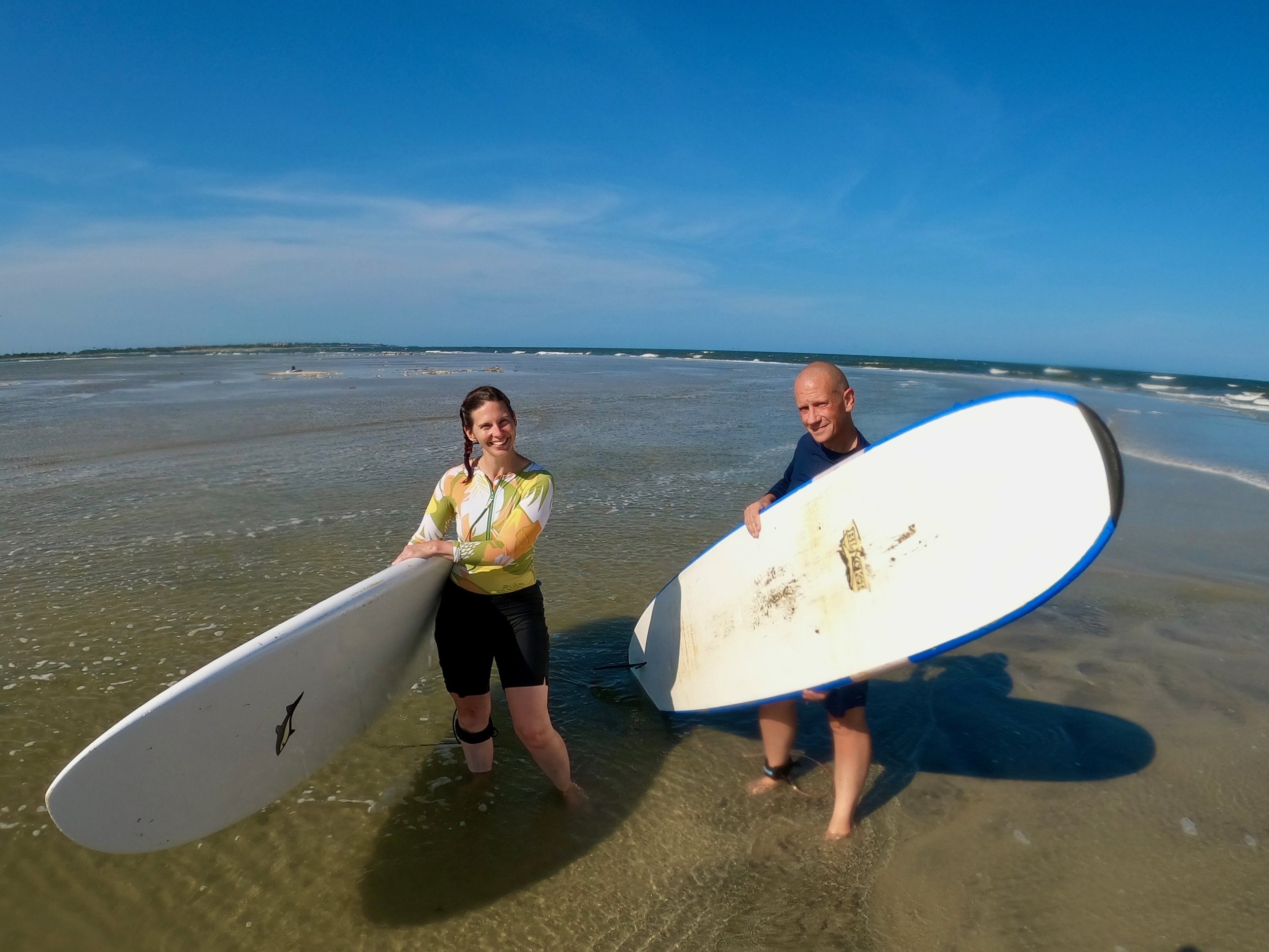
Gnarly.
We have our own boards on order!
On to the work:
Chainplates, Again
We received the chainplates from Hong Kong, but sadly they won’t work - the tangs were inadvertently drawn backwards, and since the material is already drilled for countersink holes on the exterior face, I can’t confidently flip them around and make use of them.
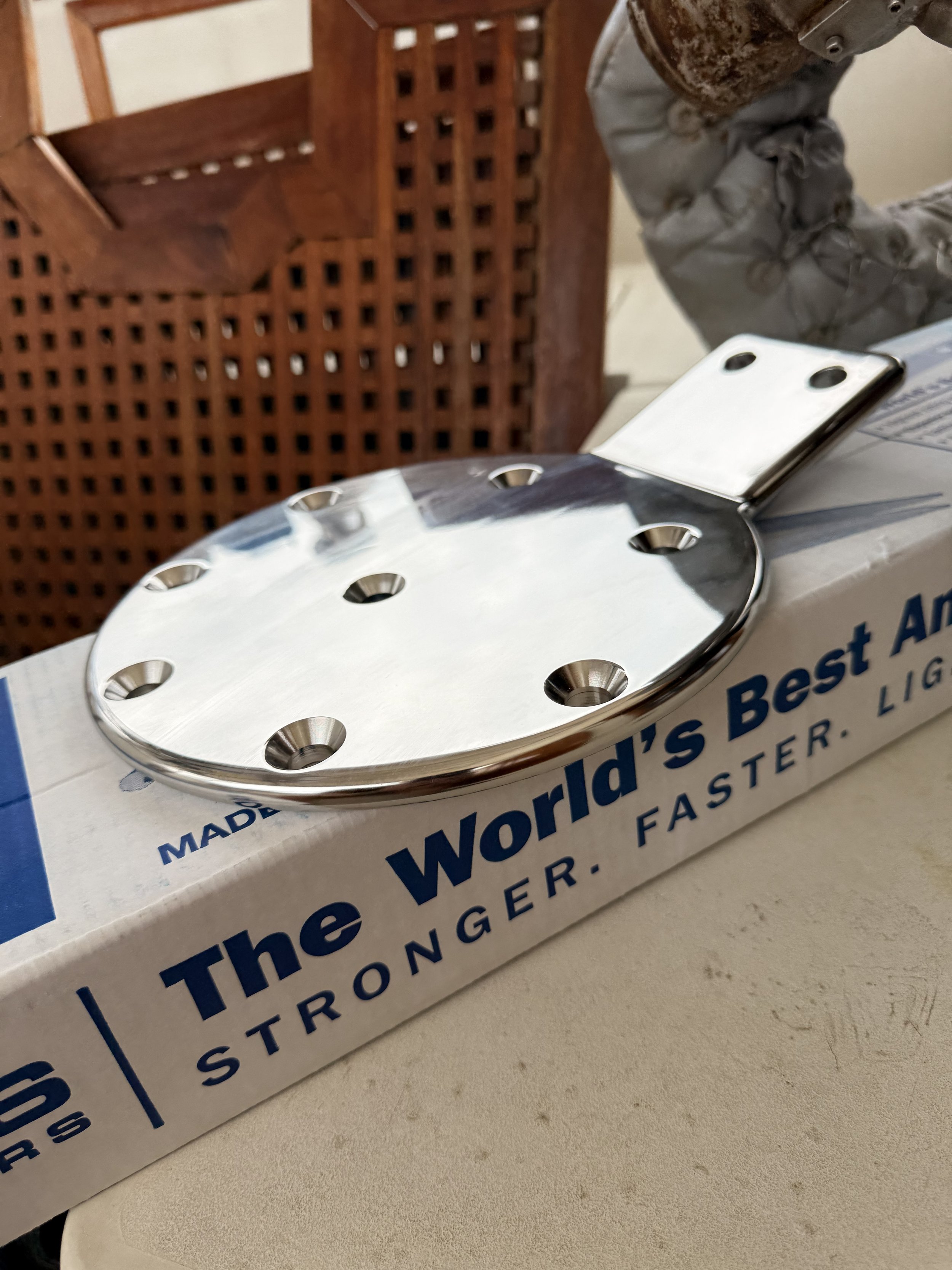
Beautiful, but backwards.
An expensive mistake on my part, and I’m incredibly grateful to my brother-in-law Michael (check out his game design company at https://goldenticketgames.com) for his help in both redrafting the CAD file and running FEA (finite element analysis) models against the plates to see what the reduction in strength for countersinking them on the opposite side would be.
Skene’s Elements of Yacht Design suggests that rigging should be deigned to take working loads of 20–25% of the standing rigging’s breaking strength, and ultimate loads of up to 60%. I estimated that the plates might see forces around 10,000lbs when the boat was flying sail in gale conditions - obviously something we’d want to avoid. However, 1x19 wire has a 30,000lb breaking strength. At 60%, the plates need to be able to withstand 18,000lbs of force, although that level is apt to only be seen on the headstay and backstay in a survival storm.
Michael’s FEA models show that even if the same countersinks were drilled into the opposite face, the plates would hold, although they would (quoting from his research) “exceed the yield strength of the steel, so there [would] be some small deformations, and you would probably want to replace them after a really bad storm like that, but you are still well below the ultimate strength of the steel so they would not break.”
I’m not willing to take the risk of potential crevice corrosion by way of those deformations, but it’s incredibly comforting to know that plates that don’t have a double-countersink will be significantly stronger, and well above the suggested maximums. In other words, our new plates will vastly exceed the strength of the original design. Another order to be placed!
Overly Detailed and Nerdy Rewiring Details
While we’re waiting on the V2 plates, I decided to dig into the electrical system. I was concerned that I could not, at any time, fully shut off power to the starter. Blue Turtle is old enough that it’s had a variety of owners, all of whom have wired things to a greater or lessor standard. She had an old battery switch, at least one bare-PCB battery combiner, a host of old flooded-lead acid batteries, and so on. These are all typical of older boats.
In preparation for going off-shore, I wanted to do three things:
Replace the FLA batteries with top-of-the-line AGMs
Do the majority of the work required to convert to lithium batteries in the future (which requires a certified electrician’s installation, per our insurance
Fully understand the existing wiring and built a proper wiring diagram
There are four main electrical sections on board Blue Turtle:
The cockpit battery compartment, which houses the house battery bank
The under-the-galley-sink compartment, which holds the engine and generator starting batteries
The primary DC distribution panel in the forward cabin
The aft nav station panel
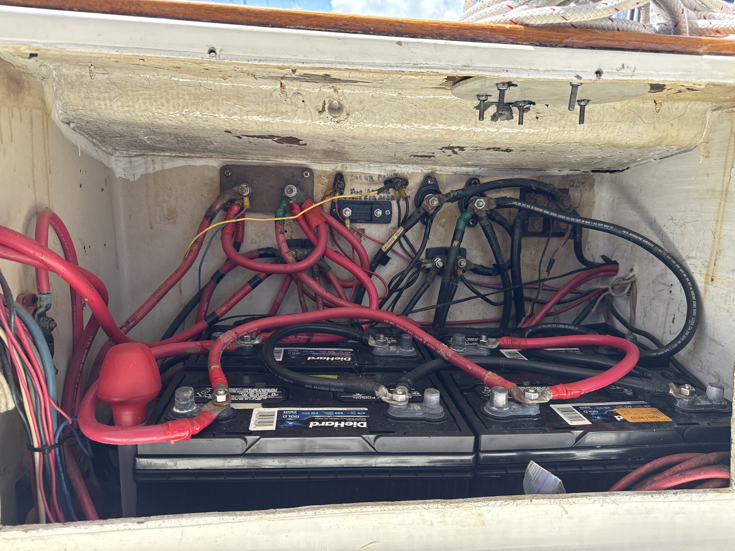
The house battery bank
The nav station
I do have a small background in electrical work, and have taken classes on DC power, so I felt comfortable starting to pull things apart. In moving from flooded to AGM batteries, I knew I also wanted to properly secure the batteries with hold-downs, fuse each battery with a Class T fuse, and setup separate disconnect switches for each bank.
I also wanted to replace a variety of old wires with new ones, especially where large wires (1/0, generally) comprised multiple connected smaller wires. Resistance in wiring generates heat, and heat leads to fires - you want the smallest runs of the largest wires you can fit (and afford), and each wire should be fused as close to the source as possible.
With a few days of meter work and boat yoga, I found a few things out:
The engine start battery was connected to the house bank via an old-fashioned battery combiner, a voltage-sensitive relay that in theory would combine the banks when the voltage on either would rise above a set point (typically ~13.3V), and disconnect them when the charge dropped.
The generator start battery was routed through the 1/1+2 selector switch
No fuses existed between any battery and its wiring
Since the house bank directly accepted solar charging, there was usually a small charge present, keeping the batteries topped up. I also found that the generator start battery was connected to the house bank, in theory allowing it to charge from the solar, but also effectively making it part of the house bank. A Xantrex Ideal regulator ran through the engine compartment, presumably to ensure that the alternator didn’t burn out when charging the house bank, and tied into the (very, very old) Heart Interface/Link 2000 battery monitor panel in the forward cabin.

The old regulator
Weirdly, there were 3 inverters aboard, one of which was a small one in the forward cabin, the other a 1980s/1990s inverter next to the primary Xantrex model, disconnected but with wires run to the battery compartment.
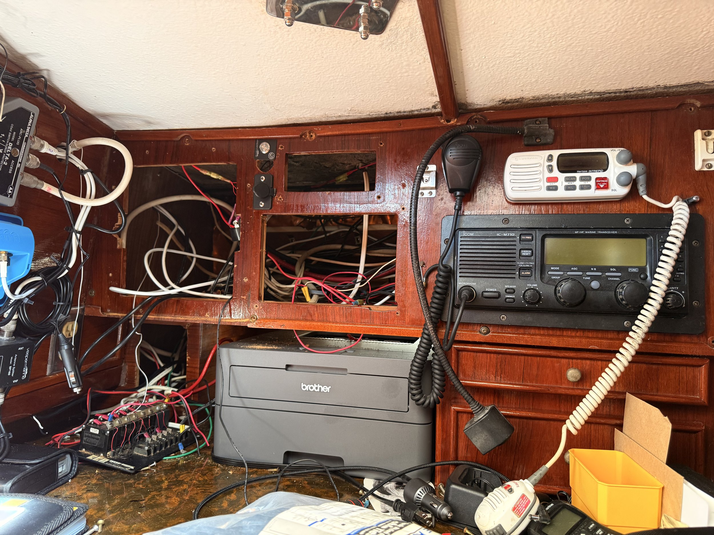
Obviously, as the photos show, all of the wiring was a mess. I found at least 3 different VHFs in the nav station! I began working by ripping out the entire nav station; I’m planning to replace the wood itself, with cutouts for our modern Raymarine gear. I also removed the ancient and non-functional SSB; we may at some point add one back, but it’ll be less than 20 years old, and with new wiring to the backstay.
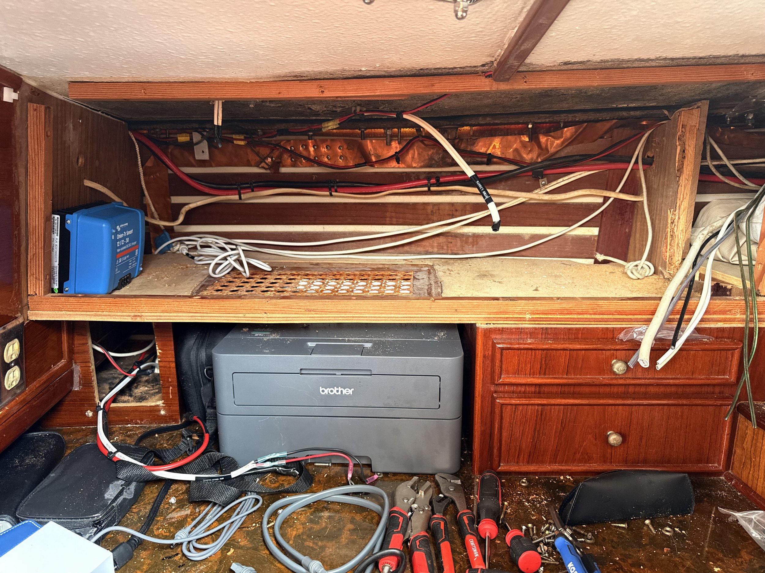
The distribution panel in the aft cabin was archaic, so I ordered a new Blue Sea panel that would fit the space. Given that the electronics connected to it (VHF, AIS, Chartplotter) are all electrically sensitive, I also setup a 12V DC-DC converter, ensuring that the aft panel would receive only clean 12V power.
Cleaning up the nav station
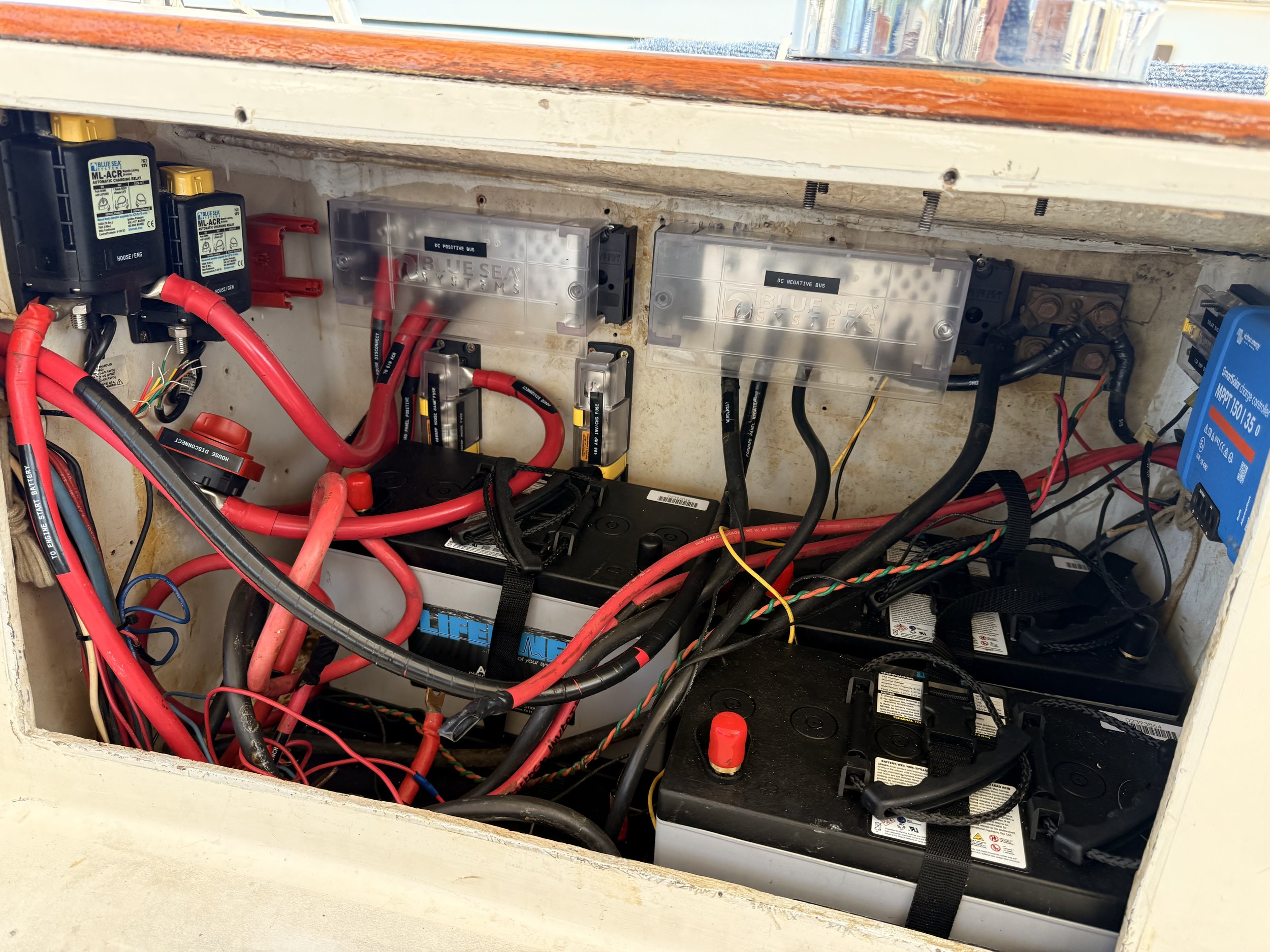
The battery compartment was, at best, confusing. I started labeling and removing each wire, pulled the old “bus bars” out, and fully rewired the entire setup with 1000amp Blue Sea busbars. I added in space for class T fuses for the main banks, the distribution panels, and the inverter charger, and have on order heavy-gauge wire for all of the batteries and panels.
I also installed hold-down straps and trays for all of the batteries, and installed Lifeline AGMs throughout the boat, giving us a 500ah house bank, and 900-ish cold cranking amps for the engine and generator start banks. I initially planned to use automatic charging relays (ACRs) to combine the battery banks after their disconnect switches, but landed on a more lithium-ready setup where the alternator charges only the engine start battery, followed by a DC-DC charger providing 50amps back to the house bank.
We’re planning to increase our solar capacity to 1000w, which should (at peak sun) provide an additional +/- 50amps to the house bank.
Work in progress…
I did leave a manually overridable ACR between the engine and generator starting batteries. Starting an engine takes a huge amount of current, but only for a very short time, so we can let the ACR combine the batteries and keep them both topped up, and in an emergency combine them to provide engine starting power if the primary battery for either runs down or has a fault.
Finally, I have a new Victron 3000w/12V inverter charger waiting to be installed, which will both provide house bank power when running as well as 120V for our outlets. Additionally, the Victron unit outputs a 4a trickle charge for the starter battery.
Running Down The Clock
We’re aiming for a mid-August launch date, so over the coming weeks I need to finish the wiring, order/receive/install the new plates and backing boards, and get the mast rewired with new electronics. The yard will continue to work on the prop shaft and through-hulls, and with luck (and a lot of sweat), we’ll be on target.
And in the interim, surf’s up…